12432 Members
237 Forums
7733 Topics
23829 Posts
Max Online: 4756 @ 02/20/20 11:12 PM
|
|
|
|
8 registered (Toysoft, Admin, Smokey, raffsif1234, Herrleon, cv64, basti, tester27),
944
Guests and
289
Spiders online. |
|
Key:
Admin,
Global Mod,
Mod
|
|
|
|
|
|
1
|
2
|
3
|
4
|
5
|
|
6
|
7
|
8
|
9
|
10
|
11
|
12
|
|
13
|
14
|
15
|
16
|
17
|
18
|
19
|
|
20
|
21
|
22
|
23
|
24
|
25
|
26
|
|
27
|
28
|
29
|
30
|
31
|
|
|
|
|
|
#7095 - 03/18/16 03:24 AM
 Re: HDMI drawing
[Re: Admin]
Re: HDMI drawing
[Re: Admin]
|

VIPF Japhar
enthusiast

Registered: 03/09/15
Posts: 218
Loc: Netherlands
|
You have forgotten to say which ESD protection (D600-D601-D603 diodes) ic has the low measurements.
And which type motherboard you have.
In any case, It could be a defective ESD protection ic, bad print track to/from the cpu, or some damage to the cpu pins, or bad cpu solder ball.
The only way to measure it is to remove the ic with the wrong measurements, and measure it without.
Most of the connections are going to the cpu and the ESD protection diodes.
6.4v question, could be due another type motherboard with newer, different dc to dc (8 pins) ic's.
These measurements are made from a older type motherboard with 16 pins (3850/N5212) dc to dc ic's.
Or, your multimeter is not accurate, or your Dc to Dc 5v ic has some issues.
Nevertheless normally it should be 5vdc.
_________________________
Doing nothing leads to nothing. ------------- Please note, for technical support ------------- Will be given here, or on the jb8a8f8 forum and I prefer it in English. Johnny B. Click on the banner if you like to go there.. 
|
|
Top
|
|
|
|
|
|
#7122 - 03/19/16 12:54 AM
Re: HDMI drawing
[Re: pashaa]
|
VIPF Japhar
enthusiast
Registered: 03/09/15
Posts: 218
Loc: Netherlands
|
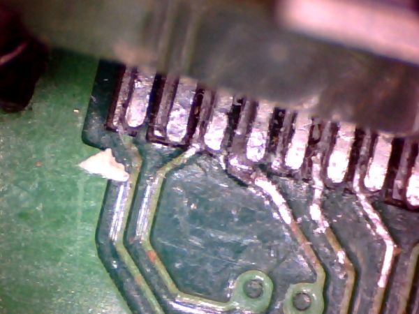
To me it seems like the entire connector is not soldered correctly.
It appears to have been placed nearly next to the pins.
Is of course to be measured, the connector solder pins should give the same Ohm value as on the D600-D601-D603 diode pins.
And mostly is the measuring red pen (probe) to thick for this job,
I have added a thin needle to it.
_________________________
Doing nothing leads to nothing. ------------- Please note, for technical support ------------- Will be given here, or on the jb8a8f8 forum and I prefer it in English. Johnny B. Click on the banner if you like to go there..
|
|
Top
|
|
|
|
|
|
#7129 - 03/19/16 06:39 AM
Re: HDMI drawing
[Re: pashaa]
|
VIPF Japhar
enthusiast
Registered: 03/09/15
Posts: 218
Loc: Netherlands
|
Yeah well, it is a sensitive area that you have to be careful.
There are lots of direct connections to the cpu, the making of a short circuit on one of the lines can be fatal.
That is why I mostly have given ohms measurements, and no vdc measurements of the sensitive lines.
But okay, maybe you are lucky and it's a diode issue.
But this you will see if you remove the diode chip, and measure the shorted line.
If it's still shorted it can be a damage of the cpu pin.
That is, if the hdmi connector pin doesn't make a short.
_________________________
Doing nothing leads to nothing. ------------- Please note, for technical support ------------- Will be given here, or on the jb8a8f8 forum and I prefer it in English. Johnny B. Click on the banner if you like to go there..
|
|
Top
|
|
|
|
|
|
#7159 - 03/20/16 11:19 PM
Re: HDMI drawing
[Re: pashaa]
|
VIPF Japhar
enthusiast
Registered: 03/09/15
Posts: 218
Loc: Netherlands
|
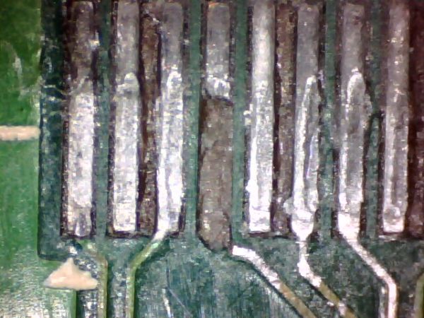
Yeah not so fine, but can be fixed with a wire. 1. Lift the pin 4 up 2. Isolate it with (kapton) tape under it from the rest and add a wire to it. 3. Add the wire on the print side to 4 D600 
_________________________
Doing nothing leads to nothing. ------------- Please note, for technical support ------------- Will be given here, or on the jb8a8f8 forum and I prefer it in English. Johnny B. Click on the banner if you like to go there..
|
|
Top
|
|
|
|
|
|
|


 Previous Topic
 Index
Index